
Prosperity that comes with the water
Agriculture has been one of the most important livelihoods for the mankind, and earth gave us our food. And water is the most important source for agriculture. Might and prosperity of the great civilizations came from the water. Egyptian, Chinese, and Mesopotamian civilizations built the most effective societies with the longest life spans on the watersides. Jazari lived in Jazaree, where was placed in the fertile crescent between the rivers Tigris and Euphrates. The deep valleys here were difficult when it came to the use of water, so all the civilizations built here searched for ways to raise the water. Jazari designed water raising systems far superior to the ones before his time, and contributed highly to the prosperity of agriculture. The five water raising systems he built – as we know today – had many innovative mechanisms like crankshaft, segment gears, double action pumps, and four-cycle mechanisms, none ever seen before his time.
Water Raising and Agriculture Historical Image
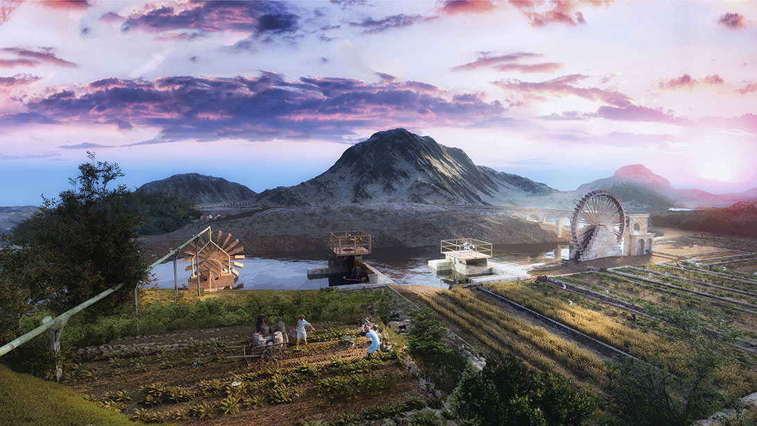
In the Middle Ages, the most important source of income for both the great empires and small city kingdoms was the agriculture, in addition to the booties of war. As we see here, Jazari contributed highly to the agricultural efforts of his time.
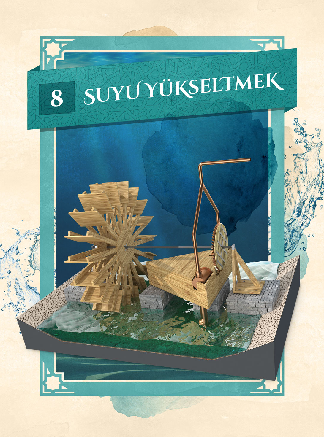
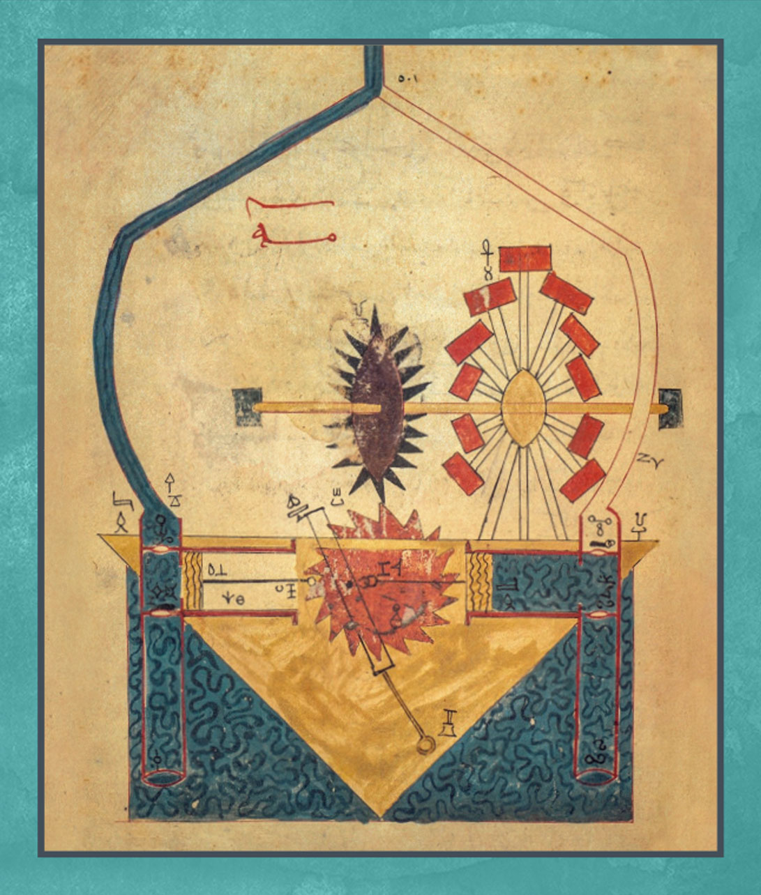
Interactive Pile Water Raising Mechanism
This mechanism that was used to raise water was actually some sort of a water wheel that was powered by animals, which was in use by many other civilizations previously with the name of Saqiah. There were large piles lined on a chain around a wheel, and as the wheel turned, the piles below took water from the source, raised it, and emptied at the top.
Instead of animals, Jazari used the water flow in this elevator water raising mechanism. Water flowing from a pool rotates the wheel called pelton turbine, and this rotation movement is transferred to the pile wheel with the gears, helping the piles to be carried upwards. You can see how it works in this model.
Try!
- Turn the arm connected to the wheel.
- You will see how the piles carry water from the pool to the top.
- When the full piles reach the top, they topple to empty the water.
- The water pours into the middle pool that is at a much higher level from the bottom.
Noria Diorama
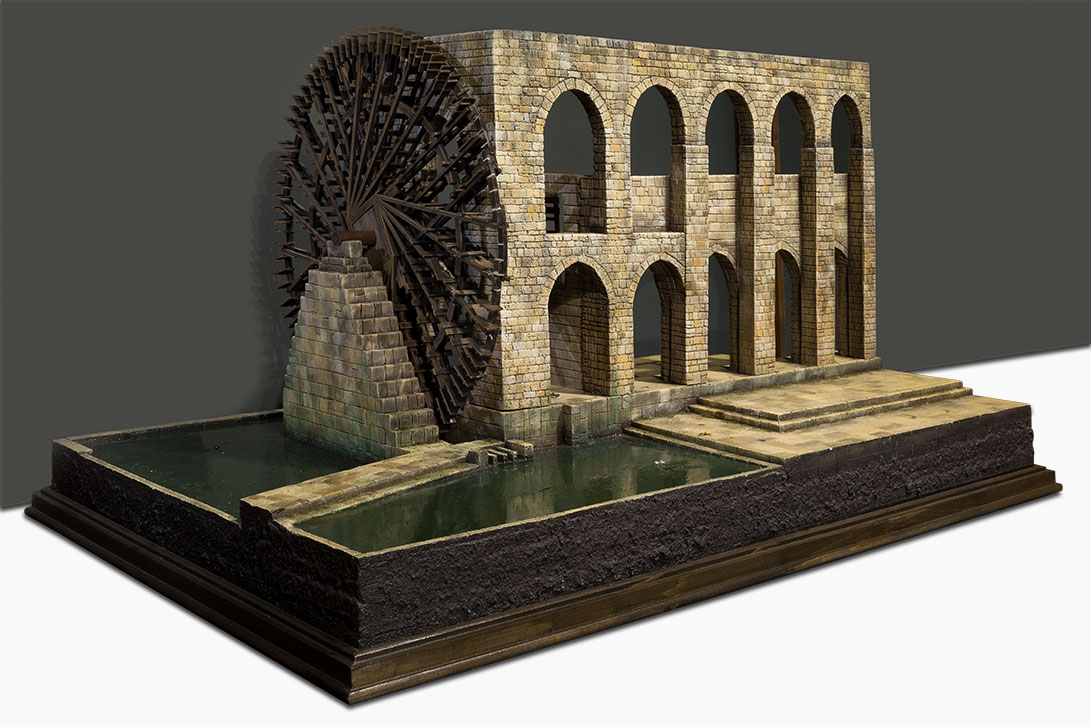
In ancient times, people who lived in drier areas used the water raising wheels to carry water from the rivers and lakes.
Noria (Ar. ناعورة) are the wheels that raise and transfer water to the aqueducts. The oldest sample was seen in Egypt in 3rd Century B.C. Today, there is still a noria wheel working in Hama, Syria. It’s diameter is 20 meter, and carries 120 piles. These wheels have been used in a lot of places from Persia to Andalusia.
Noria Wheel Water Mechanisms Historical Poster
In ancient times, people who lived in drier areas used the water raising wheels to carry water from the rivers and lakes.
Seren or shadoof (Ar. ) is a water raiser still in use in near east. It’s a leverage with a pile tied to its longer arm, and a weight on the shorter. The long arm goes into the water to fill the pile, and then the weight helps to raise the pile to empty the water into a channel at some higher level.
Sakeeyah (Ar. ) is a water wheel that is powered by animals. A pile carrying wheel is turned by mules, donkeys, or oxen to move the piles into the water to be filled. The full piles lean aside as they go up, and the water inside them pour into a main pool. Sakeeyah became very popular in Islamic civilization. According to the historian Ibn Bassal (11th Century), sakeeyah was the most popular wheel.
Tumpanon (Yun. τύμπανον), the oldest water raiser in ancient Greece and Rome, was a wheel with chambers. There were no piles in these wheels, but there were chambers inside that carried the water. There were usually eight chambers inside a wheel, and they went into the water as the wheel turned, coming up filled with water. As they move up, they empty the water into a channel through their curved ends. These wheels were powered by animals or water.
Noria (Ar. ناعورة) are the wheels that raise and transfer water to the aqueducts. The oldest sample was seen in Egypt in 3rd Century B.C. Today, there is still a noria wheel working in Hama, Syria. It’s diameter is 20 meter, and carries 120 piles. These wheels have been used in a lot of places from Persia to Andalusia.
Four Ladled Water Raiser Reconstructed
Jazari used segment gear (quarter gear) in another device that was called Four Ladled Water Raiser. While he used animal power again, Jazari included four ladles instead of one, ending up with a water raiser with much higher capacity. Other than the increase in capacity, the use of four ladles provided an amazing phasing technique. In the first system, the quarter gear was used to raise the pile to a specific point, and release it when done. In the meantime, the animal was resting with empty pile during the last three quarters of the cycle. However, in this system, quarter gear does more than that. With a change in the angular positions of the gears, each ladle does its work in turn. So, when animal completes a rotation, it raises four piles of water at once, while it carries only one pile. Looking at this phasing technique, we can say Jazari invented the concept of timed machine. Just as we saw in his fountain and sound automata, this process is repeated by segment gears that share a 360 degree cycle in equal parts. This machine is similar to the modern four-cycle engines, and can be seen as an early example. Just like as it was in the first system, an animal that has a 20-25 kg pushing force can power the entire system. With this method, an animal can raise 9.6 m3 water to 2.5 m high per hour. Since the gears in Jazari’s water raising mechanisms can transfer not only the movement but also the force, the notches of the conical gears, segment gears, and cage gears were made of metal.
Four Ladled Interactive Mechanism
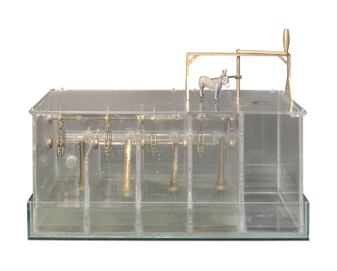
Just like the other single ladle system, this four ladle system is powered by animals, which rotate around the main driveshaft. The resulting circular movement is a horizontal movement, and the raiser mechanism is perpendicular to this. Therefore, Jazari used perpendicular gears. Changing the movement to vertical this way, it’s transferred to the segment gears. Since they have a 90 degree drive, they rotate the cage gears for only 90 degree, and release them at that point. This 90 degree phase is equal to a 90 degree raise for the ladle from the water level. Transferring the water to the draining channel, ladle freely falls back, delivering the water to the usage channel. The most important difference in this system is the fact that these four segment gears create a four-cycle machine, following each other. Thus, the animal creates 4 separate phases, and the ladle goes up at each phase. While the animal carries only one pile at a time, increasing the turnover, also the water raising capacity increases as well.
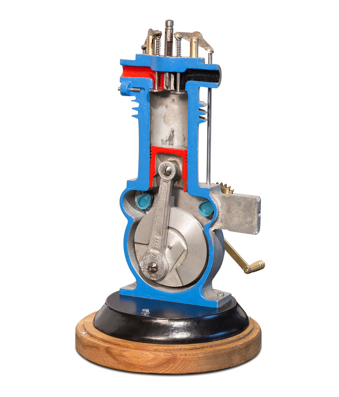
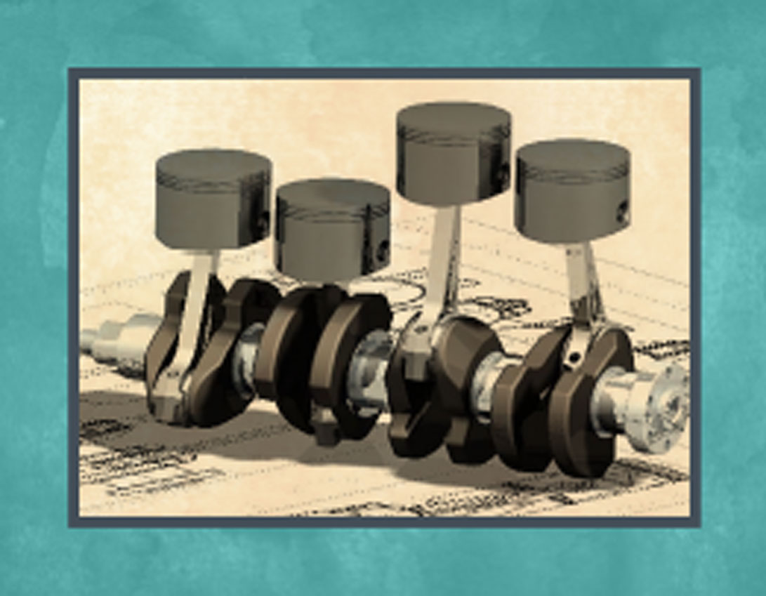
Four-Cycle Engine Mechanism
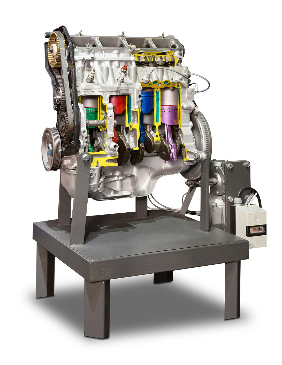
To produce power, an engine first has to transform the chemical energy into thermal energy, then use this energy to move the piston. These are the phases followed in a four-cycle engine:
1. The mix of fuel and air fills in the empty space by the outwards move of the piston.
2. Karışım pistonun içeri hareket etmesiyle sıkıştırılır.
3. In the gasoline engines, the pressurized mix is ignited by a spark, and it ignites itself by the high pressure and heat in the diesel engines. With the resulting energy, piston is pushed outwards, which causes the rotation of the crankshaft, creating the kinetic energy.
4. As the piston goes back, the exhaust valve is open, and gas is thrown out through the exhaust pipes. Cycle goes back to the first position, and the cycle is repeated.
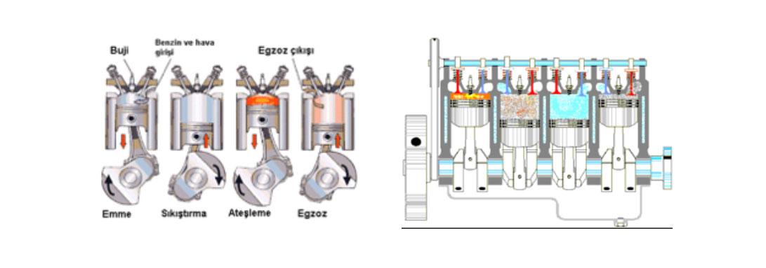
This is same for each piston inside the engine. Considering a 4 piston engine, we can see that the rotation force is applied to the crankshaft at different times. In another word, these four pistons are positioned in different times of the cycle. We see a 4 piston engine in the figure.
1. When the pressurization is complete
2. During the ignition
3. During the sucking
4. During the exhaust outflow
Interactive Segment Gear Mechanism
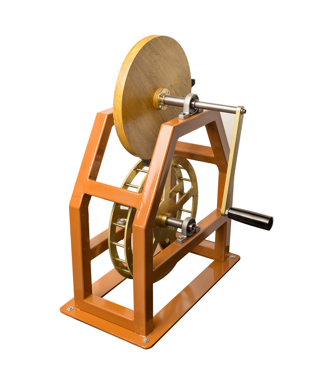
This is a segment gear mechanism that enables the four ladled water raiser to raise its ladles at different times. Differently than normal gears, only specific parts of the gear have notches. And with these notches, with the circular movement, cage gear moves only at specific times. At the sections where there are no notches, cage gear loses the movement effect other than its own pendulum. Segment gears are limited gears that can apply force at different times in a sequence, or at different places.
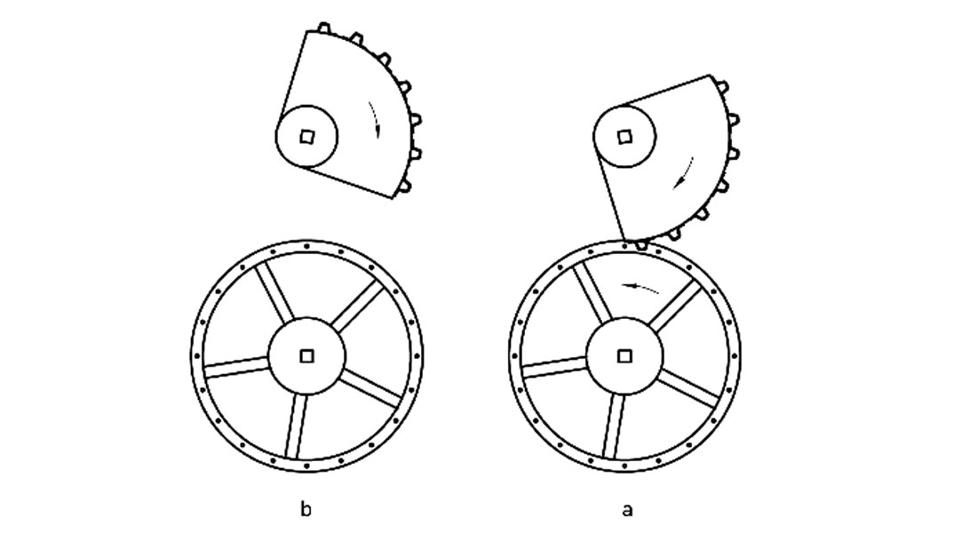
Here in this mechanism, there is a gear where notches are inserted at only a quarter part, and below it, a cage gear system – a gear system where the gears are connected to each other with sticks.
Try!
- Turn the lever attached to the segment gear.
- This rotation will be transferred to the segment gear, and then to the cage gear.
- Segment gear rotates on its own at specific intervals.
- When the notches meet each other, the gears turn together.
Water Raiser CGI Animation
In this short video, you can observe how Jazari’s water raising machines that were used by the Artuqid worked.
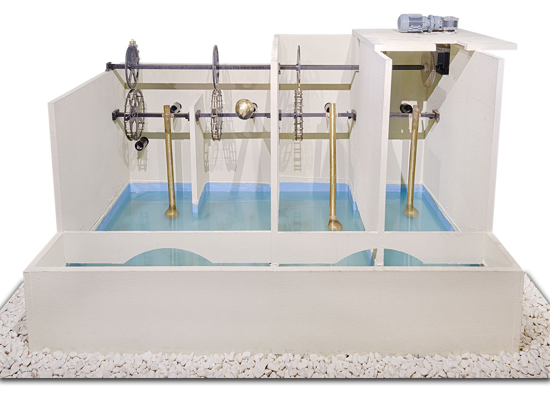
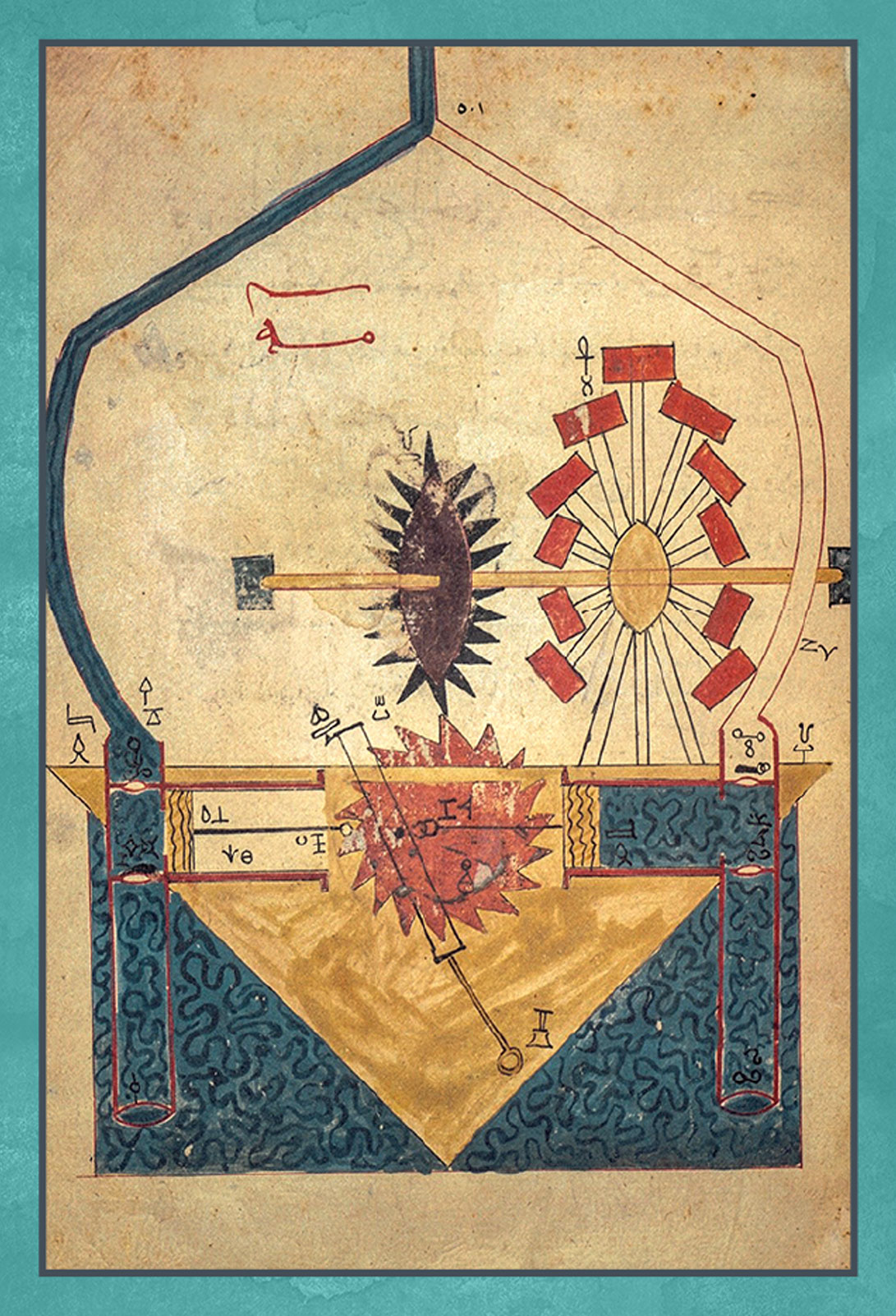
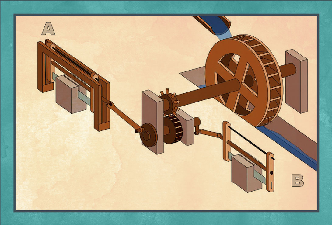
Interactive Double Action Water Pump
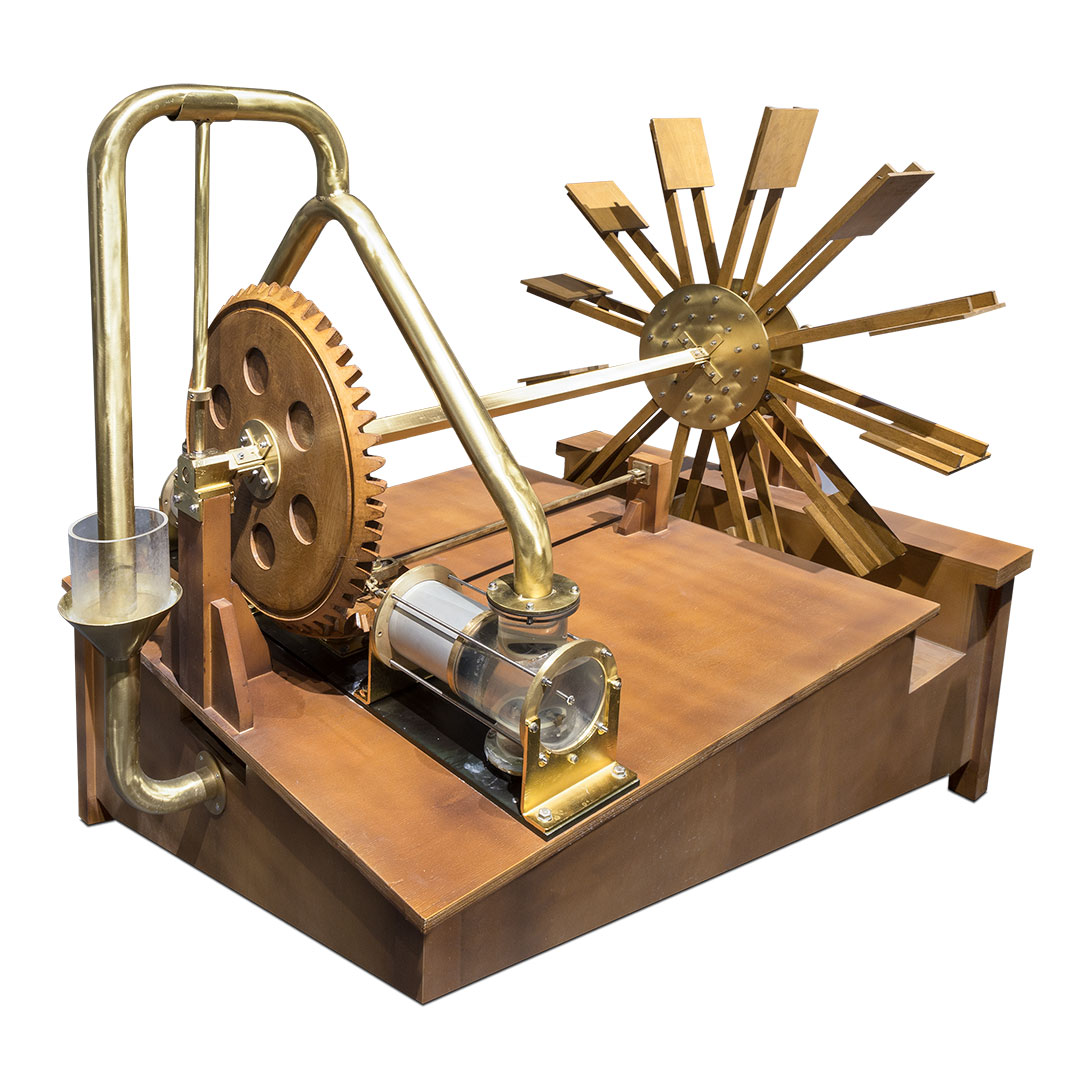
This water pump by Jazari was the most important device of its own time with its contributions to the agriculture. Other than its high economical value during its own time, this device also represents some highly advanced technology.
The shaft of a winged wheel is built on a river. As the paddled wheel turns, the shaft turns a vertical gear, and that turns another horizontal gear. As this second gear turns, a pin attached on the top follows a circular movement, moving a special stick through its slit end. And the arms connected to the sides of this end moves the pistons of the cylinders inside a box. As each piston is pushed down to the bottom of its cylinder, another is pulled up.
The cylinders in this mechanism work as suction pumps. Since a vacuum is created at the bottom of each cylinder as the piston is pulled up, the flap of the sucking pipe is open, while the flap of pushing pipe is closed. When the cylinder is full of water through the sucking pipe, the lower flap is open and water is pumped upwards.
Working together, the two pumps send 22 m3/hour water to 10 meter high. Both for the amount of water, and for the height, this machine was highly advanced in technology for its own time. On the other hand, while the sucking pumps have a water supply problem, this machine works continuously due to its double action feature.
How Does It Work?
The shaft of a winged wheel is built on a river. As the paddled wheel turns, the shaft turns a vertical gear, and that turns another horizontal gear. As this second gear turns, a pin attached on the top follows a circular movement, moving a special stick through its slit end. And the arms connected to the sides of this end moves the pistons of the cylinders inside a box. As each piston is pushed down to the bottom of its cylinder, another is pulled up.
Worthington Pump Animation
You can see the working principle of Worthington Pump in detail.
Worthington Pump and Other Historical Pumps Poster
Water is the pushing force for the entire nature. Water was essential for the existence of all civilizations. To secure the water for higher places required energy. Since the energies like electricity or fossil fuel were unknown, people had to invent manual mechanical tools or machines run by natural power like wind or water. Such water raising machines have been throughout the entire history.
Water raising machines always existed all around the world since 3000 B.C. Primitive systems like water wheels or gutters were built to provide the energy needed for wheels, and animals (muscle energy) were widely used. Afterwards, some different pumps like helium pumps – also known as “Archimedes” – were invented, and they are still in use today. Moreover, various water raising machines like “tympana” were widely used in irrigation and mining until the last century.
We can summarize some of the most popular water raising machines in chronological order as below:
SHADOOF (4000 B.C. – 67 A.D.)
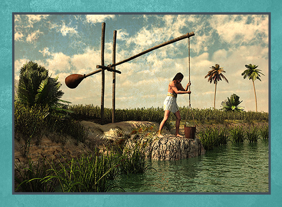
This machine that was called shadoof was used manually to raise water from a well, a river, a cistern, or a channel. In its most popular form, it’s made of a wooden shaft that looks like a leverage.
WATER WHEEL (700-600 B.C.)
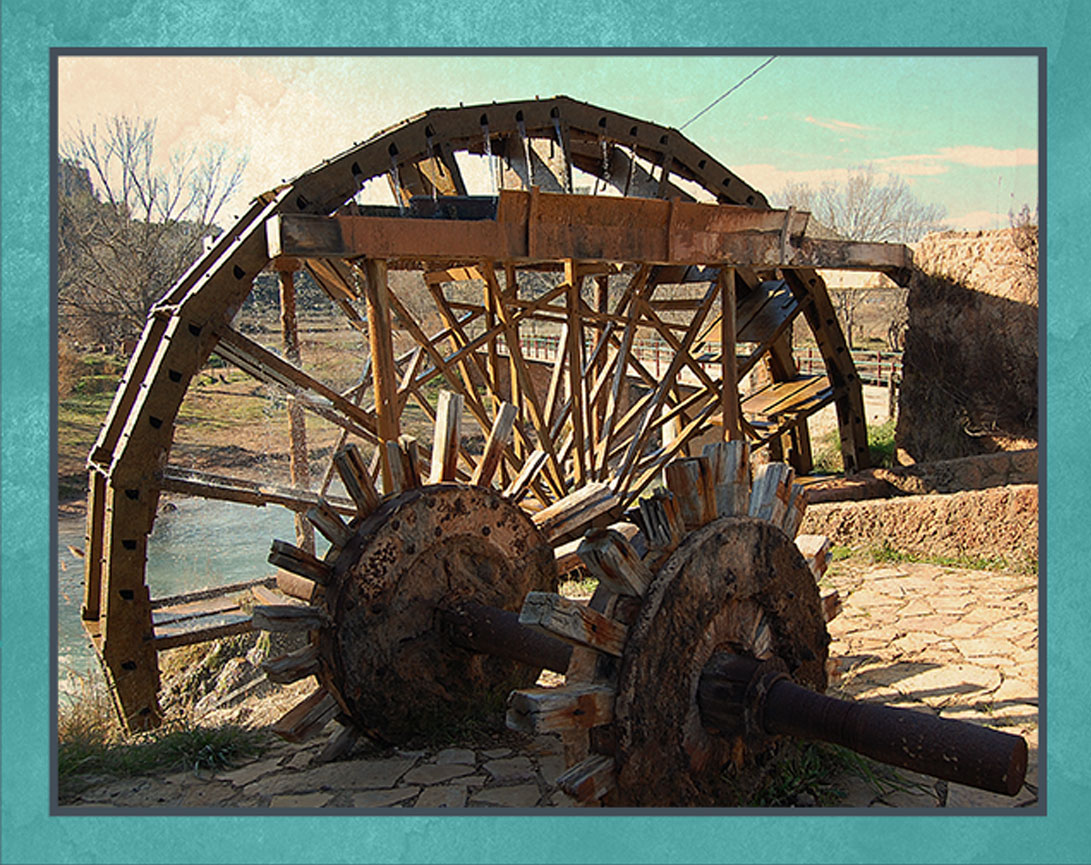
Noria (Ar. ناعورة) are the wheels that raise and transfer water to the aqueducts. The oldest sample was seen in Egypt in 3rd Century B.C. Today, there is still a noria wheel working in Hama, Syria.
ARCHIMEDES INFINITE SCREW (287-212 B.C.)
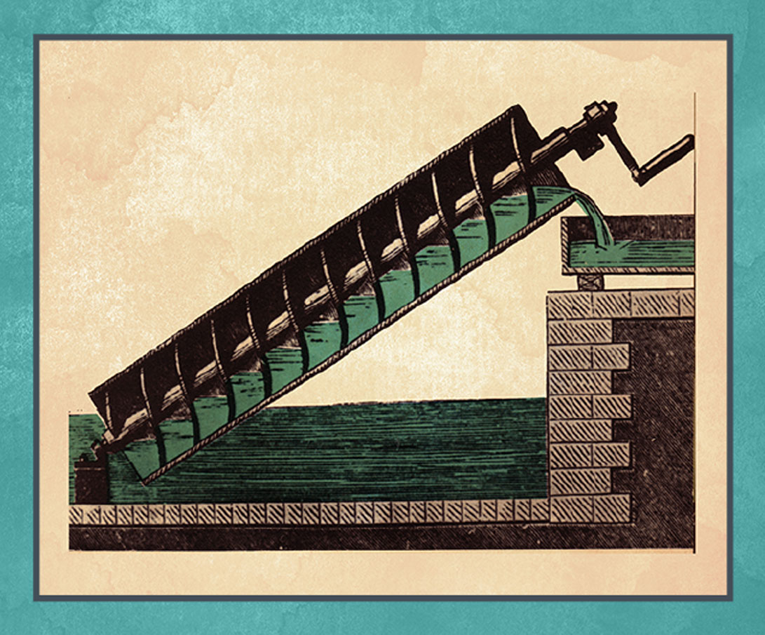
This infinite screw that is known mathematician and engineer Archimedes – but not his invention – was a mechanical devices used to raise water.
KTESIBIUS SUCTION AND FORCE PUMP (285-222 B.C.)
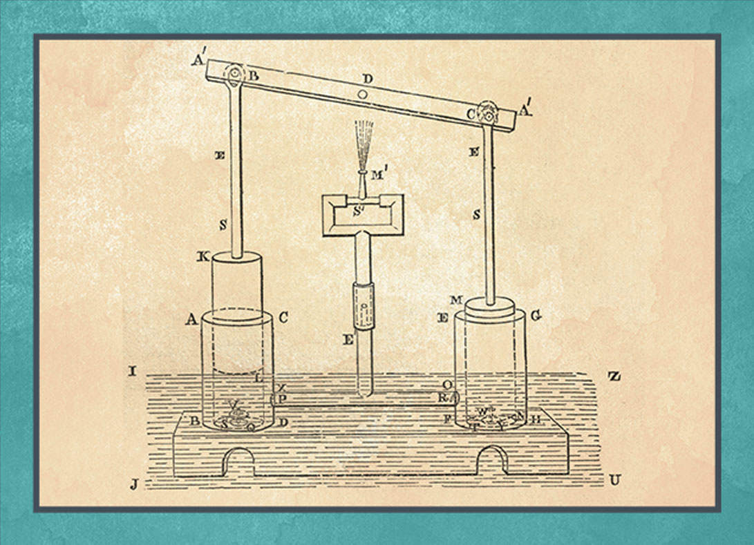
The principle of suction and force pump is very simple. Water is pumped through a one direction valve, and with the movement of a piston, it’s directed to a transfer pipe by another one direction valve.
JAZARI’S DOUBLE ACTION PUMP (1136-1206)
The shaft of a winged wheel is built on a river. As the paddled wheel turns, the shaft turns a vertical gear, and that turns another horizontal gear. As this second gear turns, a pin attached on the top follows a circular movement, moving a special stick through its slit end. And the arms connected to the sides of this end moves the pistons of the cylinders inside a box. As each piston is pushed down to the bottom of its cylinder, another is pulled up. This creates a continuous water flow pumped up to 10 m high. This system is the first crankshaft mechanism known in the history.
OTTO VAN GUERICKE PISTON VACUUM PUMP (1640-1650)
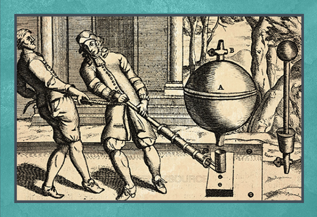
These pumps are essentially water pumps that work in opposite directions. The vacuum created by the sudden drainage of the water inside a spherical chamber sucks water from the other piston.
HENRY R. WORTHINGTON – STEAM PUMP (1840-1855)
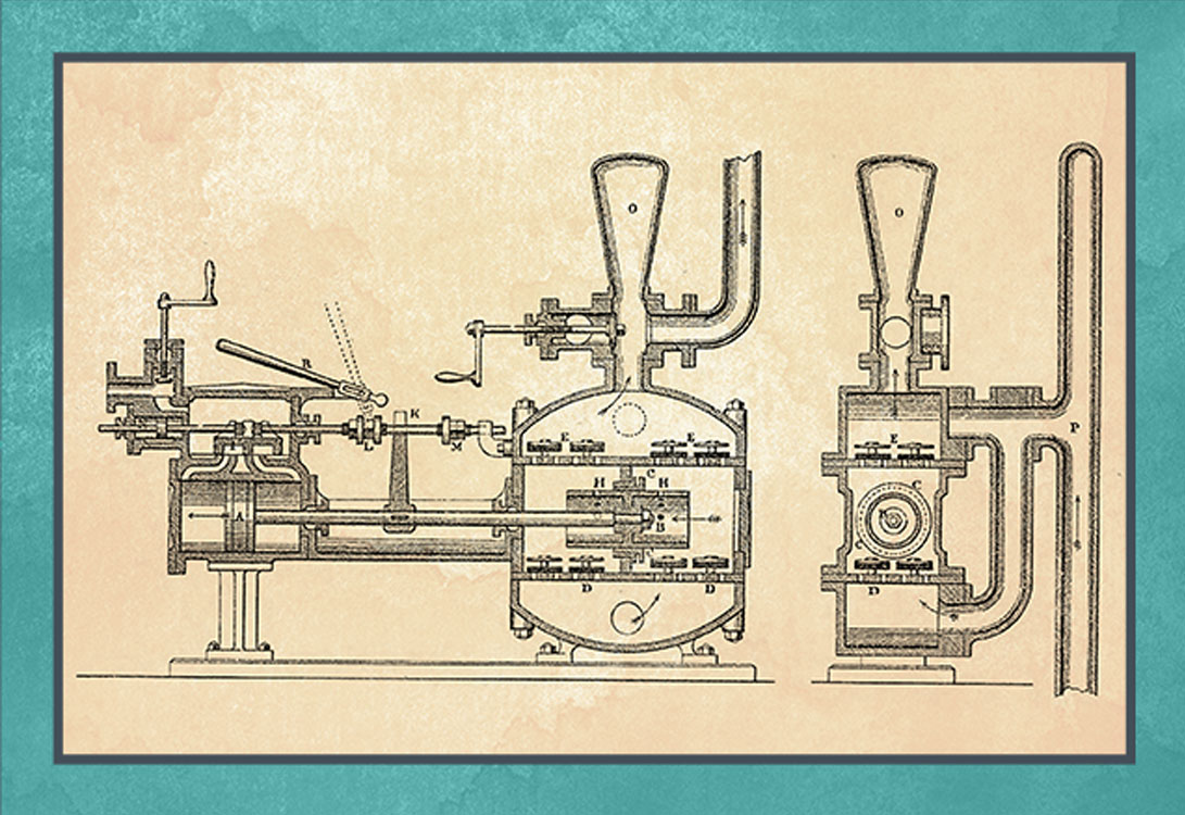
After James Watt invented the steam engine, Worthington combined his piston pumps with the steam engine, and developed the first direct action steam pump. This pump, which is also known as one direction steam pump, is made of a steam engine connected to a double action water pump. As the piston of the engine moves back and forth, it pushes and pulls the piston of the water pump, and the water is pushed through the valves placed along the valves. With this double action feature, it gives the impression that Worthington might have been inspired by Jazari’s machine.
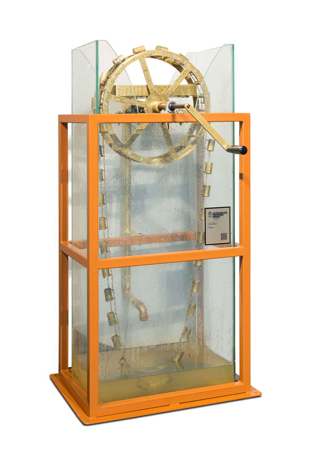
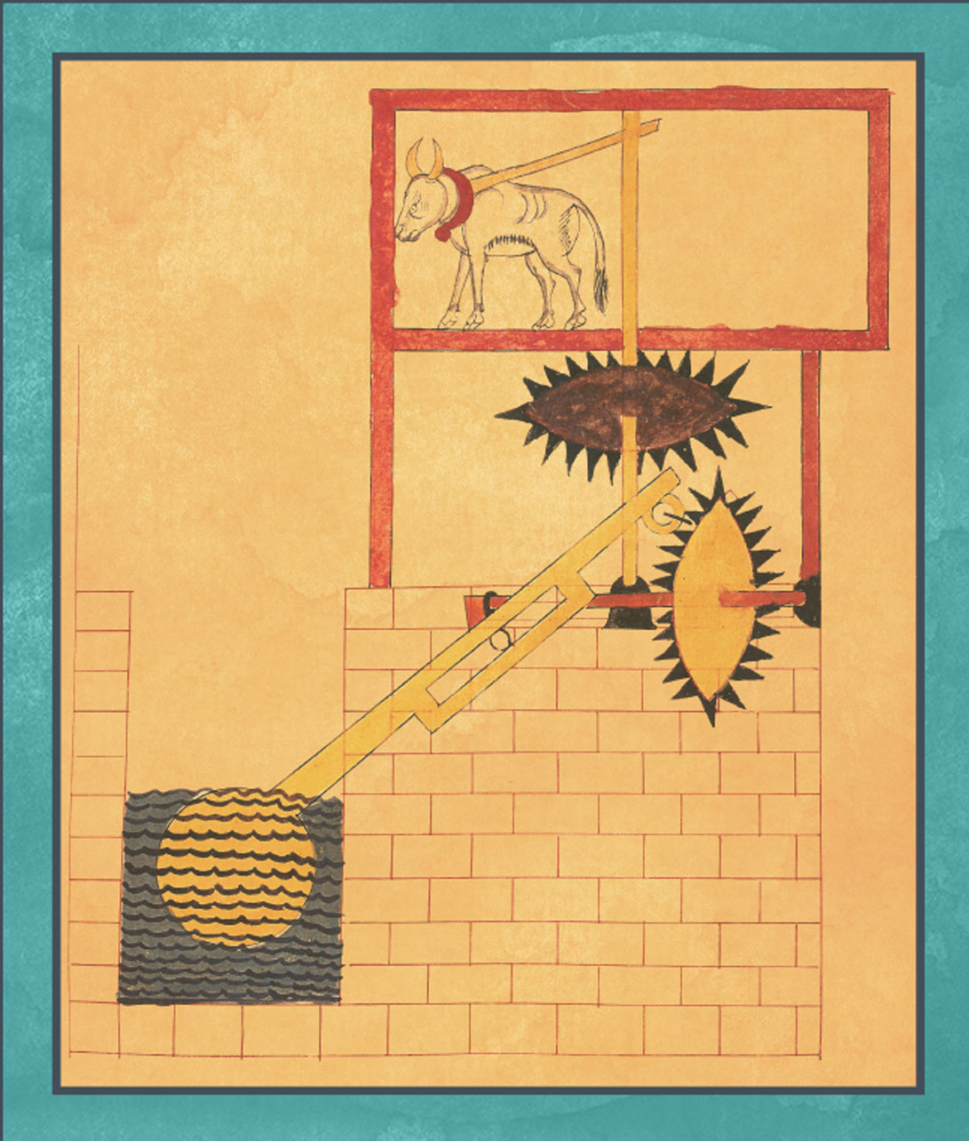
Interactive Crankshaft Water Raising Mechanism
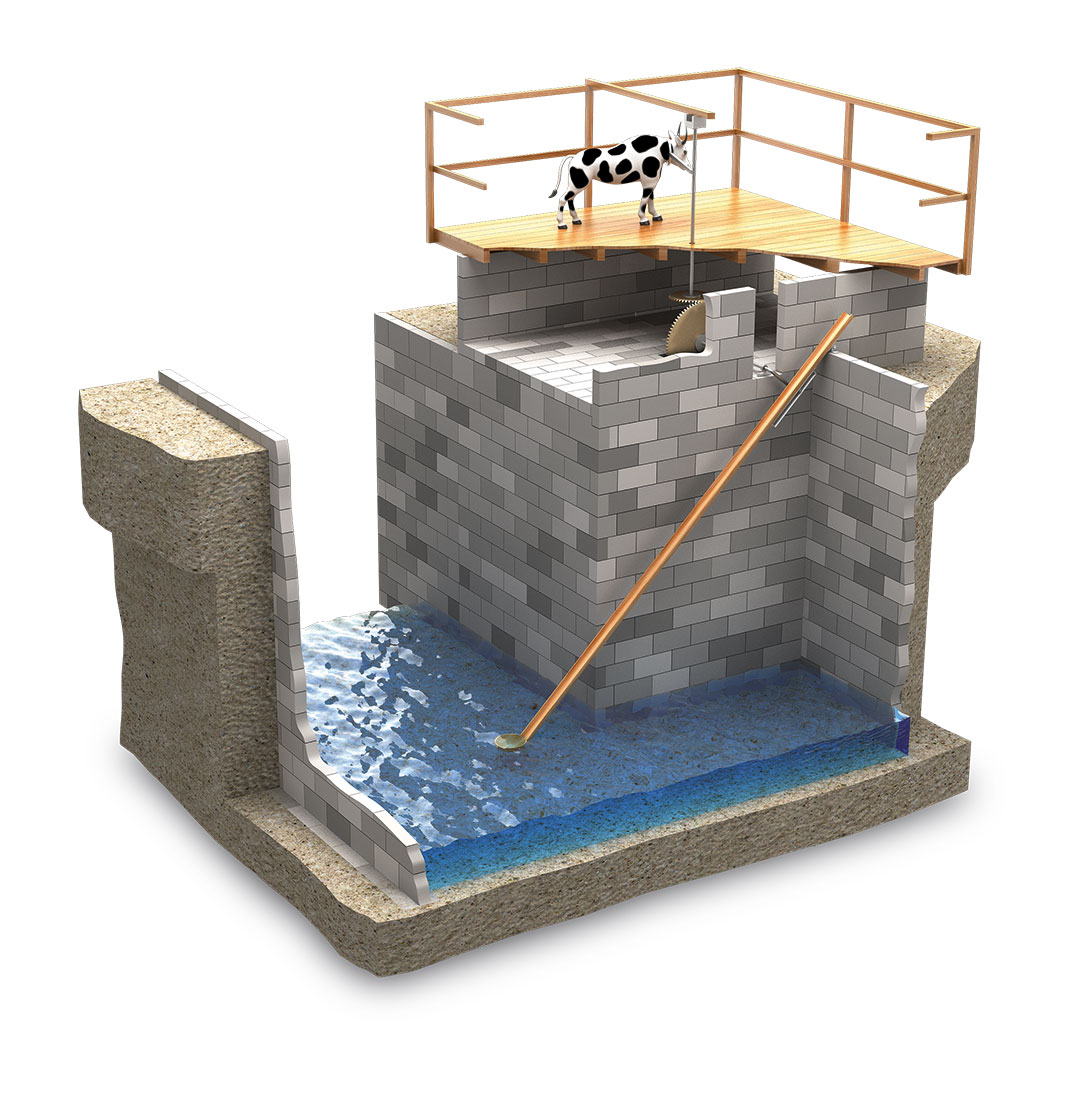
This system that triggers the ladle here is different than segment gears. Here in this instance, Jazari developed the crankshaft that is very important in engine industry today. The historical importance of this system is the fact that it boasts the crankshaft that transforms the linear and circular movements back and forth 300 hundred years prior to we see it in Western Europe. Ladle is bigger with a 22.5 liter volume, and it can raise the water 5 meters high. In his book, Jazari drew an ox bigger than normal beef cattle powering this machine. Indeed, this device requires a more powerful animal that can pull 75 kg. Since it also requires a larger diameter in its circular movement, the animal must be really strong. Again, the vertical gear that is powered by the animal here transforms the energy to the horizontal shaft through a gear with conic notches. One end of the shaft is bent, applying a hub here. This end moves the ladle back and down with the horizontal movement of the shaft. In the meantime, it pours the water inside into the channel in the land. Here, the first circular movement becomes a back and forth movement. When the ladle empties its water by segment gears, the gear is released from its cage, so that ladle falls with its own weight. In this occasion, though, ladle moves completely by the movement of the animal, and the ladle moves connected to the slider all the time. Since the animal here is bigger than the others, its slower pace with 2 rotations per minute can be acceptable. Considering the friction would be higher in this device, it’s calculated that it can raise 1.5 m3/hour water to 5 meters high.
Interactive Crankshaft Mechanism
This crankshaft model was made by “Classroom Materials Center” that made classroom tools for all the high schools. Since the establishment no longer exists, the model has been sent to the engine divisions of the trade schools. This model explains the working principle of the car engines (gas or diesel) that uses crankshafts most. While you can see one full rotation of the crank, you can also observe the movements of valve that fuel and air go through.
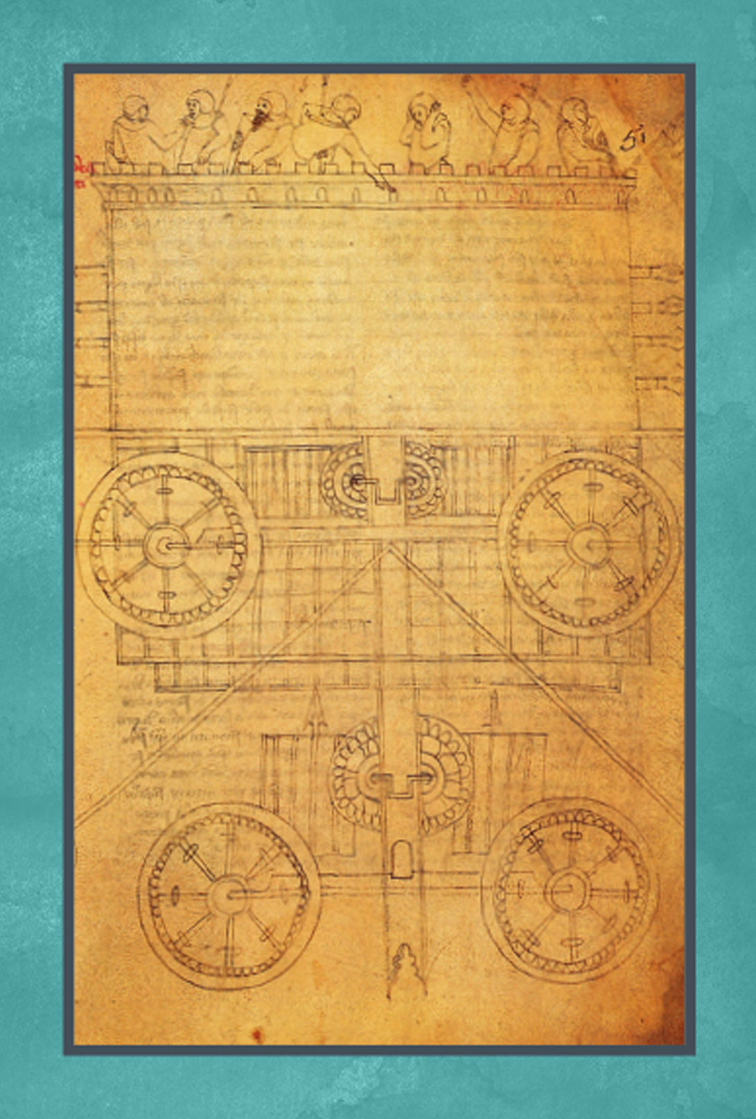
Crankshaft Poster
Crank is a lever that is connected to shaft at right angle, and it can transforms between circular and linear actions back and forth.
• The first manual crank was seen in China 3th Century B.C, and the Chinese used this crankshaft first in agricultural winding mills.
• Single rod combined crankshaft was seen in Hierapolis lumber factory in Asia, 3rd Century B.C., and two stone saw in Rome, 6th Century B.C.
• Jazari first used the crankshaft as a crank slider mechanism for the ladled water raiser. Crankshaft was connected to a gear system that was powered by cattle, and the ladle could raise the water with a quarter rotation of the gear.
• Afterwards, developing the crankshaft slider mechanism a little bit more, Jazari made the double cylinder pump with double action crank-rod mechanism for the first time in engineering history.
• Italian doctor Guido da Vigevano made some illustrations that showed oar boats and chariots that were moved by combination crank and gears.
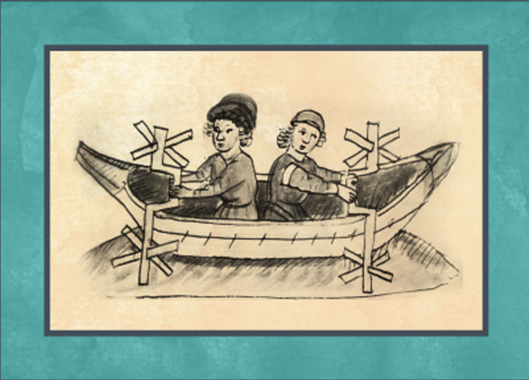
• The combined crank boats we see among the war machine drawings were developed by Italian engineer and author Roberto Valturio, and he designed a boat with five sets. All the parallel cranks were connected to the same power source by a rod system.
• Again around the same centuries, crankshaft toothed rack devices were used that were attached to the crossbow handles.
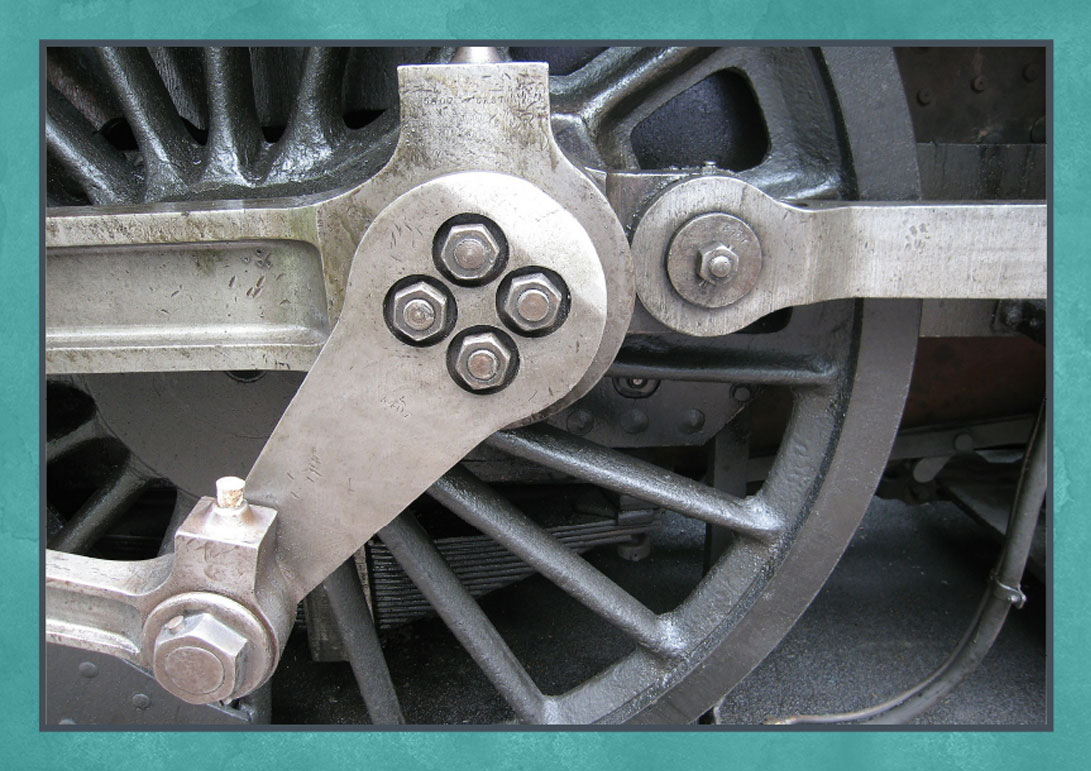
• After the invention of steam engines, crank-rod combinations were used for the transformation of the circular and linear movements of the pistons in cylinders. They are still in use for the making of internal combustion engines.

Water Direction Device and Pool Sprinkler
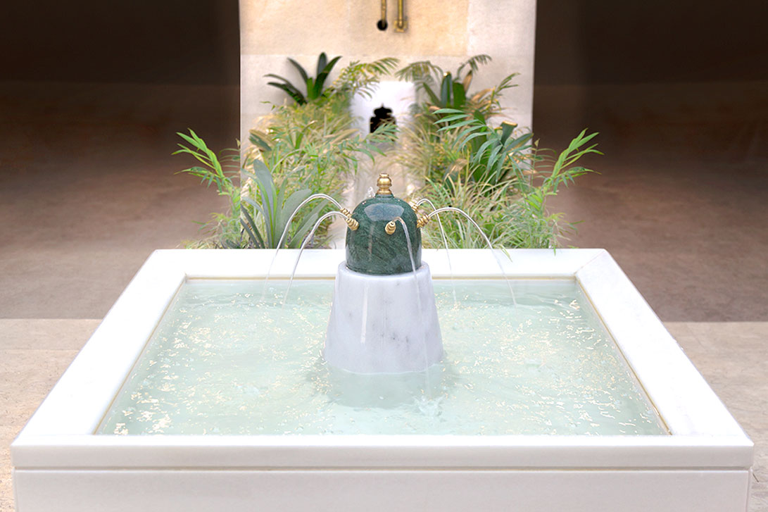
This device is explained by Jazari in the end of sprinkler section, but he wrote that it can be used both in the sprinklers and the zemr (whistle). Indeed, this device can be used for all the water direction mechanisms. Jazari describes this mechanism as “a single mechanism” that is “weird and surprising.” The flow is divided here in a way that while the thin pipe fills the spoon, and the water coming out the thicker pipe is directed to the pipelines or pressurizing chamber of a zemr. The first spoon falls over when full, and the other spoon begins to fill. With this falling movement, the water direction is changed, and a sphere attached cylinder is used for the balance.
Flow Control Mechanism
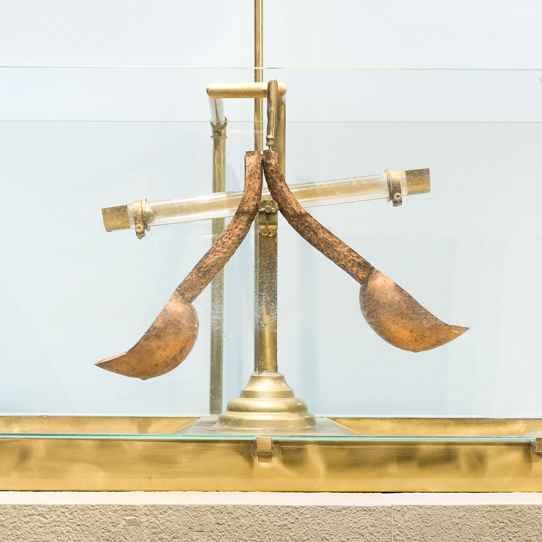
This mechanism is one of the most important examples to the variational actions of the sprinklers that are installed in pools, as a garden decoration. The flow is divided here in a way that while the thin pipe fills the spoon, and the water coming out the thicker pipe is directed to the pipelines or pressurizing chamber of a zemr. The first spoon falls over when full, and the other spoon begins to fill. With this falling movement, the water direction is changed, and a sphere attached cylinder is used for the balance.
OBSERVE!
- You can see that, in the flow control mechanism, the water continuously flows in one direction.
- The water goes into the pool through a hole, and comes out through a sprinkler.
- You also see that some amount of water also flows through a small pipe to fill the ladle.
- When the ladle is full, the weight changes the balance, and it turns the flow direction to the other way.
Classic Gardens Poster

Cennetin Yeryüzündeki Gölgesi: Bahçeler
Throughout history, gardens have been the symbol of glory, permanence, and beauty. Babylon’s gardens are still remembered despite the 2500 year of time that has passed. Luxembourg Gardens in Paris, and Hyde Park in London are modern examples of gardens. Gardening is a tradition that expanded from India to Spain, covering the entire Islamic culture, beginning in 8th Century. So much that the there is a sort of poetry called ravsiyah in Arabic literature, which is based on the idea that the gardens are the heavens on earth.
The palace gardens of Baghdad with their walls surrounding hundreds of acres, the city where was a center of science, culture, and commerce in 9th Century, fountain gardens of Samarra, orchards of Damascus, and tulip gardens of Topkapi Palace are some of the most important examples of Islamic gardening tradition.
We also shouldn’t forget the amazing gardens of Alhambra Palace in Granada, Andalusia. Alhambra Palace that rose on the top of the ruins of a military headquarters in 14th Century is important both for its architecture, and its characteristics in gardening. On the top of a hill where water didn’t exist, fruit and plants previously unknown to Spania were grown, and the gardens were decorated with large pools. This beautiful decorations that gave Alhambra an immortal glory were possible only the water raising technology in addition to botanic knowledge. The mechanical knowledge of water control that was improved by Jazari and other Muslim scientists created lots of means so that many applied sciences like gardening, not only in Andalusia, but the entire Islamic regions.